miércoles, 7 de noviembre de 2018

Post 4. Physical Computing chaps.1 &3

Image result for philip guston
Philip Guston, Painter's Head, 1975. Private collection. © The Estate of Philip Guston

Citas:

Introduction:-
How computers see us:


 To change how the computer reacts to us, we have to change how it sees us
/*This also applies to our relation with audiences; the mode of representation we choose conveys a (un)limited way of comprehension and interaction*/

Just in the act of standing up, a person effortlessly reveals
important details through hundreds of subtle and unconscious adjustments every second.
Even though these expressions come and go very quickly, humans have amazing abilities
for reading into this body language the interior state of another person. To make the
computer a medium for expression, you need to describe the conversation you want to have
with (or better yet, through) the computer.

Concepts:
Most physical computing projects (and most computer applications in general) can be broken down into these same three stages: listening, thinking, and speaking—or, in computer terms: input, processing, and output. Breaking down your project along these lines will enable you to better focus on your particular challenges.


Chapter 1: Electricity

Palabras clave: Transducción; Energía

Citas:
 Looking at it from a high level, you’re converting the intentions of the participant into action. At a lower level, you’re converting the physical energy he or she exerts into electrical energy so that a computer can sense it.
 
All electrical and electronic devices exploit the fact that electrons have a tendency to go
from a point of greater electrical energy to a point of lesser electrical energy. You provide
a positive connection (greater energy, or power), a negative connection (lower energy, or
ground), and a conductor through which the electrons flow.

Electrical energy always follows the path of least resistance to ground. The better the conductor, the easier it is for the electrons to flow. The point of lowest electrical energy is the earth itself, which is where we get the term “ground.” 

 The light bulb resists the flow of that energy, converting
it into heat and light. In a well-designed circuit, all the electrical energy gets converted into
some other form of energy by devices like light bulbs, heaters, and so on.

 A switch is a break in the circuit that stops the electrons from flowing. By closing the switch, you close the break in the circuit and allow the electrons to flow again

There are three basic electrical characteristics that come into play in every circuit. The
relative level of electrical energy between any two points in the circuit (for example,
between power and ground) is called the voltage. Voltage is measured in volts. The
amount of electrical energy passing through any point in the circuit is the current.
Current is measured in amperes, or amps for short. The amount that any component
in the circuit resists the flow of current is called the resistance of the component.
Resistance is measured in ohms. Voltage, current, and resistance are all related, and they
all affect each other in a circuit (see sidebar).

 As previously mentioned, a circuit is a closed loop, so all the energy that comes in from the battery has to get used up somehow by the resistance of your load. If your circuit does not use enough energy, it will just go right back into the battery, heating it up, and eventually blowing it up.

 The combination of current and voltage is called electrical power, or wattage. It’s measured in watts. The relationship is straightforward: watts = volts × amps (likewise, amps = watts/volts or volts = watts/amps). For example, a 120-watt light bulb would need 1 amp at 120 volts.2
The amount of wattage you supply to a circuit determines how much work it can do. The more work you need to do, the more power you need.

In this case, you’re using the
change in electrical energy to pass a message
or a signal. For our purposes, this is the distinction between electricity and electronics.
Think of electronics as a subset of electrical circuits that is used to convey information.
electronic circuits don’t need a lot of electrical power. They just need enough power to register a message in a brain or in another computer by turning on small things like an LED or a transistor...
 On the other hand, when you use electrical energy to do physical work, such as turning on motors, you need much more electrical power. For this reason, you’ll find that the input components of your projects will generally need less power than the output components. 
 A direct current (DC) source supplies current on one wire and ground on another, and the voltage between them is constant with the supply wire always at a higher voltage. An alternating current (AC) source alternates the voltage on the two wires. It’s easier to supply electrical energy over very long wires using AC, which is why commercial electrical power is AC. The power coming out of your electrical socket is typically 120 volts AC in the United States and 220 volts AC in Europe and Asia. Electronic components generally operate using DC, however, and at a much lower voltage, typically around 5 volts. They generally need very little amperage as well (less than one amp for most of the circuits you’ll build), so we use AC-to-DC converters and transformers to change alternating current to direct current. The large, blocky power supplies that come with most electronic devices are AC-to-DC converters/transformers that convert the 120/ 220 volts AC to around 5 to 12 volts DC.

How Electricity Flows
 
Electricity always favors the path of least resistance to ground

All the electrical energy in a circuit must be used. Any extra energy will get converted to heat by your components. If there’s too much energy, the components will overheat and stop working.


 All of the electricity follows this path because it’s the only path. In this circuit, the light bulb, which is the only component that uses electrical energy, has to consume all of the electrical energy. In this circuit, the battery, the switch, and light bulb are all in series with each other, meaning that they are all on the same electrical path. When components in a circuit are in series, the current is the same for each of them, but the voltage decreases as each component uses some of it up.

Since the smaller light bulb offers a path of less resistance, some of the current goes through it and some goes through the big light bulb, so both bulbs are a bit dimmer than they would be if they were alone in the circuit. These light bulbs are in parallel with each other, meaning that they are on two different electrical paths in the circuit. When components are in parallel, the current is split between them, depending on their relative resistances. The more resistance a component has, the less current goes through it. The voltage across them is the same, though.

 In this one, we’ve added a bare wire in parallel with the
two light bulbs, as shown in Figure 1.3. Since the bare wire has almost no resistance,
almost all of the current goes through it. This is the dreaded short circuit.


Chapter 3. Building Circuits

We will keep the circuitry to a minimum, just enough to get a transducer’s signal into the microcontroller. Once the signal is in the microcontroller, you can do in software a lot of the logical work that used to be done in circuitry.
The schematic is more abstract than the drawing, which gives you minimal information about each component. The first step in reading a schematic is to decode the schematic symbols.

Image result for connection symbols schematics
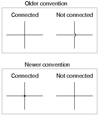
Conexión de cables, el punto de conexión se llama juntura (junction).
 
Image result for power symbols schematic
Power Sources Schematics

 
Image result for ground symbols schematic
Ground Symbols
 

 there are thousands of sensor and actuator circuits available online produced by other microcontroller hobbyists and professionals. You may be tempted to use a schematic or a kit for a standalone device, such as a lie detector or a light organ. These circuits are more complicated than you need because they rely on a lot of circuitry to route, transform, and perform logic on the signals.

Breadboards:
The basic model, with many horizontal rows separated by a central divider and one or two long side rows, called bus rows, is the type that we’ll focus on.

The reason for the center divider is so that you can mount integrated circuit chips, such as microprocessors, on the breadboard.
Image result for breadboard
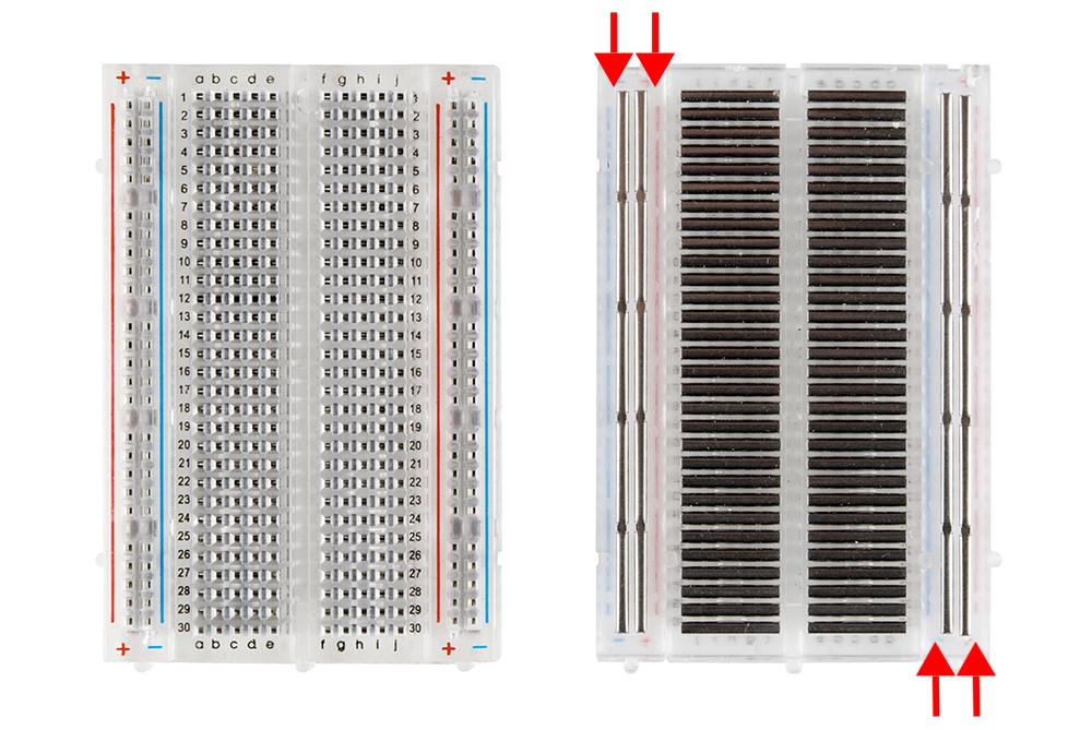
Breadboard, pins and internal plates.

CAUTION When you start to put components on your breadboard, avoid adding, removing, or changing components whenever the board is powered. You risk damaging your components by accidentally pushing two wires together and causing a short circuit. Later, if you have AC power, or larger DC power, running through your circuit you could also seriously shock yourself. 

It’s best to place your chip toward the top. Generally the lower pins get to do most of the work, and it’s good to have some extra breadboard real estate near them. Make sure that that the legs actually make their way into the hole and don’t get caught on the edge, bending up behind the chip. If you have to take the chip back out, pry it gently from both ends using a flat bladed screwdriver. The pins are easily bent, and the more you bend them, the more likely they are to snap off.

Arranging electronics (Interpreting schematics).
Wherever there is a junction in your schematic, you must join all the components connected to that junction. The most common problems arise when you treat the schematic as a geographic map of what the circuit should look like. The schematic indicates how components are connected electrically. The spatial arrangement of the components in the circuit may not match the spatial arrangement in the schematic, but all of the connections must match up.

Voltage Regulators:
Related image

 The 7805 regulator is used to take a varying range
of voltage (from 8 to 15 volts DC) and convert it to 5 volts DC. It can supply almost 1000
milliamps of current (1 amp) at 5 volts, assuming the power supply that’s feeding it can
supply up to an amp as well. The pins of the regulator are numbered from left to right as
you look at the front of it (the side with the label), as shown in Figure 3.19. Pin 1 is the
input pin, which you connect to the 8 to 15 volts of the power supply. Pin 2 is the ground,
which you connect to the ground of the power supply and to the ground of your circuit.
(The metal top of the regulator is also a ground. This will be helpful later when you are
looking for a ground connection to touch with your multimeter probe.) Pin 3 is the output
pin. This outputs 5 volts. Connect this pin to the voltage side of your circuit.

Be neat:
Image result for neat breadboard
Use cable ties to anchor your power connector (and any future
wire connecting to the outside world) to something stationary on your board. This strain
relief will make it less likely that your circuit will be disconnected accidentally when your
power cord inevitably gets tugged as you connect and disconnect your project. Figure 3.21
shows the right way and the wrong way to wire a board.


martes, 30 de octubre de 2018

Post 4 Ejercicios Tinkercad (3) Manejar un Led RGB

En este ejercicio, nos dispondremos a modificar el color de un Led RGB, por medio de el control de sus parámetros de emision.

IMAGEN 1: Esquema de led RGB, notese las distintas entradas controladoras de cada espectro de color.


El circuito comprende la posibilidad de excitar cada entrada del Led independientemente, por medio de distintos pines de salida de la placa Arduino.

Materiales:
1x Arduino Uno
1x Protoboard
1x LED - RGB Catodo
3x 330Ω Resistencia
5x Cables tipo jumper

IMAGEN 1, La segunda entrada del Led se conecta a GND, mientras que la primera, tercera y cuarta entrada se conectan con los pines 9,10,11 del Arduino respectivamente. Atención a que cada entrada incluye una resistencia fija de 330 ohms.

El código que programa la incidencia de cada canal es el siguiente:

const int RED_PIN = 9;
const int GREEN_PIN = 10;
const int BLUE_PIN = 11;

const int DISPLAY_TIME = 1000;  // used in mainColors() to determine the 
// length of time each color is displayed.

void setup()    //Configure the Arduino pins to be outputs to drive the LEDs
{
  pinMode(RED_PIN, OUTPUT);
  pinMode(GREEN_PIN, OUTPUT);
  pinMode(BLUE_PIN, OUTPUT);
}

void loop()
{
  mainColors();        // Red, Green, Blue, Yellow, Cyan, Purple, White
  //  showSpectrum();    // Gradual fade from Red to Green to Blue to Red
}

/******************************************************************
 * void mainColors()
 * This function displays the eight "main" colors that the RGB LED
 * can produce. If you'd like to use one of these colors in your 
 * own sketch, you can copy and paste that section into your code.
/*****************************************************************/
void mainColors()
{
  // all LEDs off
  digitalWrite(RED_PIN, LOW);
  digitalWrite(GREEN_PIN, LOW);
  digitalWrite(BLUE_PIN, LOW);
  delay(DISPLAY_TIME);

  // Red
  digitalWrite(RED_PIN, HIGH);
  digitalWrite(GREEN_PIN, LOW);
  digitalWrite(BLUE_PIN, LOW);
  delay(DISPLAY_TIME);

  // Green
  digitalWrite(RED_PIN, LOW);
  digitalWrite(GREEN_PIN, HIGH);
  digitalWrite(BLUE_PIN, LOW);
  delay(DISPLAY_TIME);

  // Blue
  digitalWrite(RED_PIN, LOW);
  digitalWrite(GREEN_PIN, LOW);
  digitalWrite(BLUE_PIN, HIGH);
  delay(DISPLAY_TIME);

  // Yellow (Red and Green)
  digitalWrite(RED_PIN, HIGH);
  digitalWrite(GREEN_PIN, HIGH);
  digitalWrite(BLUE_PIN, LOW);
  delay(DISPLAY_TIME);

  // Cyan (Green and Blue)
  digitalWrite(RED_PIN, LOW);
  digitalWrite(GREEN_PIN, HIGH);
  digitalWrite(BLUE_PIN, HIGH);
  delay(DISPLAY_TIME);

  // Purple (Red and Blue)
  digitalWrite(RED_PIN, HIGH);
  digitalWrite(GREEN_PIN, LOW);
  digitalWrite(BLUE_PIN, HIGH);
  delay(DISPLAY_TIME);

  // White (turn all the LEDs on)
  digitalWrite(RED_PIN, HIGH);
  digitalWrite(GREEN_PIN, HIGH);
  digitalWrite(BLUE_PIN, HIGH);
  delay(DISPLAY_TIME);
} // esta es una lista de todos los colores que puede producir el LED según el intervalo correspondiente. Notar que cada valor es digital (binario)

/******************************************************************
 * void showSpectrum()
 * 
 * Steps through all the colors of the RGB LED, displaying a rainbow.
 * showSpectrum() calls a function RGB(int color) that translates a number
 * from 0 to 767 where 0 = all RED, 767 = all RED
 *  
 * Breaking down tasks down into individual functions like this
 * makes your code easier to follow, and it allows. 
 * parts of your code to be re-used.
/*****************************************************************/

void showSpectrum()
{
  for (int x = 0; x <= 767; x++)
  {
    RGB(x);      // Increment x and call RGB() to progress through colors.
    delay(10);   // Delay for 10 ms (1/100th of a second) - to help the "smoothing"
  }
}

/******************************************************************
 * void RGB(int color)
 * 
 * RGB(###) displays a single color on the RGB LED.
 * Call RGB(###) with the number of a color you want
 * to display. For example, RGB(0) displays pure RED, RGB(255) 
 * displays pure green.
 * 
 * This function translates a number between 0 and 767 into a
 * specific color on the RGB LED. If you have this number count
 * through the whole range (0 to 767), the LED will smoothly
 * change color through the entire spectrum.
 * 
 * The "base" numbers are:
 * 0   = pure red
 * 255 = pure green
 * 511 = pure blue
 * 767 = pure red (again)
 * 
 * Numbers between the above colors will create blends. For
 * example, 640 is midway between 512 (pure blue) and 767
 * (pure red). It will give you a 50/50 mix of blue and red,
 * resulting in purple.
/*****************************************************************/
void RGB(int color)
{
  int redIntensity;
  int greenIntensity;
  int blueIntensity;

  color = constrain(color, 0, 767); // constrain the input value to a range of values from 0 to 767

    // if statement breaks down the "color" into three ranges:
  if (color <= 255)       // RANGE 1 (0 - 255) - red to green
  {
    redIntensity = 255 - color;    // red goes from on to off
    greenIntensity = color;        // green goes from off to on
    blueIntensity = 0;             // blue is always off
  }
  else if (color <= 511)  // RANGE 2 (256 - 511) - green to blue
  {
    redIntensity = 0;                     // red is always off
    greenIntensity = 511 - color;         // green on to off
    blueIntensity = color - 256;          // blue off to on
  }
  else                    // RANGE 3 ( >= 512)- blue to red
  {
    redIntensity = color - 512;         // red off to on
    greenIntensity = 0;                 // green is always off
    blueIntensity = 767 - color;        // blue on to off
  }

  // "send" intensity values to the Red, Green, Blue Pins using analogWrite()
  analogWrite(RED_PIN, redIntensity);
  analogWrite(GREEN_PIN, greenIntensity);
  analogWrite(BLUE_PIN, blueIntensity);
}

Imágen: El programa hará un incremento en los valores de cada rango de color. Colores secundarios como el púrpura son obtenidos de la proporción intermedia entre 2 rangos.

Post 3: Ejercicios Tinkercad (2) Leer un Potenciómetro

El objetivo de este ejercicio es poder leer la resistencia variable que genera un Potenciometro, en el momento en que una corriente (5V) es transmitida a través de este. Utilizando una entrada de la placa Arduino, podremos determinar la cantidad de corriente que ingresa según la resistencia asignada al potenciometro.

Materiales:
1x Arduino Uno R3 conectado a un computador por medio de un cable USB
1x Protoboard
1x LED
1x  Resistencia 330Ω
2x Cables tipo Jumper
1x Potenciometro

IMAGEN 1: Componentes. El potenciometro posee  entradas, siendo la del medio la que utilizaremos para transmitir las medición de resistencia.


Conectamos los componentes a la protoboard, asegurando que las lineas de corriente (+) y de tierra (-) se encuentren "puenteadas" (cada linea roja conectada a la salida de 5v, y cada linea negra conectada a GND).
El potenciometro debe estar conectado en sus entradas exteriores a 5V y GND respectivamente. La salida central se guiará al puerto analogo A0, que será configurado como INPUT. A su vez, el puerto 13 será configurado como salida, que se conectará con el anodo del LED.
IMAGEN 2: Conexiones que comunican la protoboard con la placa Arduino.


A continuación, ingresaremos el código en la placa Arduino. El potenciometro enviará un valor de resistencia variable análogo, al Pin A0, dicho valor modulará el tiempo de delay() entre el estado HIGH/LOW del Led.


int sensorPin = A0;    // The potentiometer is connected to analog pin 0                  
int ledPin = 13;      // The LED is connected to digital pin 13
int sensorValue;    //We declare another integer variable to store the value of the potentiometer

void setup() // this function runs once when the sketch starts up
{
  pinMode(ledPin, OUTPUT);//definimos la salida 13 como OUTPUT
}

void loop() // this function runs repeatedly after setup() finishes
{
  sensorValue = analogRead(sensorPin); //Designamos la lectura del lector como un valor int(entero), obtenido del potenciometro)    

  digitalWrite(ledPin, HIGH);     // Turn the LED on
  delay(sensorValue);             // Pause for sensorValue in milliseconds (Cada intervalo está modulado por la variable sensorValue, recibida desde el pin A0
  digitalWrite(ledPin, LOW);      // Turn the LED off
  delay(sensorValue);             // Pause for sensorValue in milliseconds} 

IMAGEN 3: Circuito en operación. Los intervalos se regulan según el valor de la resistencia variable del potenciometro.


lunes, 29 de octubre de 2018

Post 2: Ejercicios Tinkercad (1) Blinking a LED


En este apartado, doy cuenta de los primeros ejercicios en electrónica utilizando la plataforma Tinkercad.


Ejercicio1, Blinking a LED: Realizaremos este experimento como una introducción a las fundamentales de la programación electrónica.
Materiales:
1x Arduino Uno R3 conectado a un computador por medio de un cable USB
1x Protoboard
1x LED
1x  Resistencia 330Ω
2x Cables tipo Jumper

  Image result for led catodo anodo

Notas: El ánodo es la entrada positiva de corriente, el cátodo es su salida. Arriba se encuentran todas las marcas de identificación en el LED.


IMAGEN1: Componentes del experimento (Arduino uno, Protoboard, resistencia 330 ohms, Led Rojo)


En este diagrama, podemos comprobar como la placa Arduino alimenta con 5V desde su salida POWER, conectada a la hilera izquierda Positivo (+), la electricidad pasa por el ánodo del LED, saliendo por su cátodo conectado a la hilera Negativo (-), por medio de la Resistencia de 330ohms.
La hilera negativa a su vez está conectada a la salida GND de la placa Arduino.


A continuación, programaremos el comportamiento del LED, mediante el uso del Puerto (PIN) 13.
Para ello, debemos designarlo como salida {pinMode(13, OUTPUT);}
A su vez, determinaremos su encendido y apagado por medio de los comandos
 {digitalWrite(13, HIGH); }{ digitalWrite(13, LOW);}
Y la velocidad de intervalo por medio del comando {delay(1000);}

A continuación incluiré el código en su totalidad:

void setup()
{
  pinMode(13, OUTPUT); //establecemos el pin 13 como salida de voltaje
}

void loop()
{
  digitalWrite(13, HIGH);   //Prende el LED, conectado por medio del PIN13
  delay(1000);              // Espera 1000 milisegundos
  digitalWrite(13, LOW);    // Apaga el LED  
  delay(1000);              // Espera 1000 miliseguindos.
}

IMAGEN 2: Nuevo circuito, el cable verde conecta la salida (pin 13), con el Anodo del LED.

IMAGEN 3: Led Encendido, demostrando el intervalo de 1 segundo entre estados HIGH/LOW.

Link Ejercicio: https://www.tinkercad.com/things/394z9zpxhoc-daring-juttuli-snaget/editel?tenant=circuits

Post 1. Intro


El siguiente Blog comprende los ejercicios y procesos relacionados con el curso de Seminario impartido por Carola Pino A.  durante el segundo semestre del Magíster en Artes Mediales.


Daniel Estrada (1985) tiene una doble Licenciatura en Artes Visuales (2017) y Lengua y Literatura Inglesas (2007).  Su paso por ambas carreras ha decantado en el estudio y experimentación con los signos que conforman nuestra identidad  (personal y comunitaria) dentro del contexto transhistórico actual.
Ideas: Identidad; Globalidad/Localidad,;Lengua  oficial/ vernácula; Memoria; Simulación; Territorio ;Material/Inmaterial.